
When different metals are joined, and there is a temperature difference between them, a magnetic field occurs between the joints where the different metals meet. The heat of the pilot flame is the source of the temperature difference in a normal pilot system. Through this process, a small amount of current is produced. There are different types of metals used to produce a variety of voltage vs. Temperature scales.
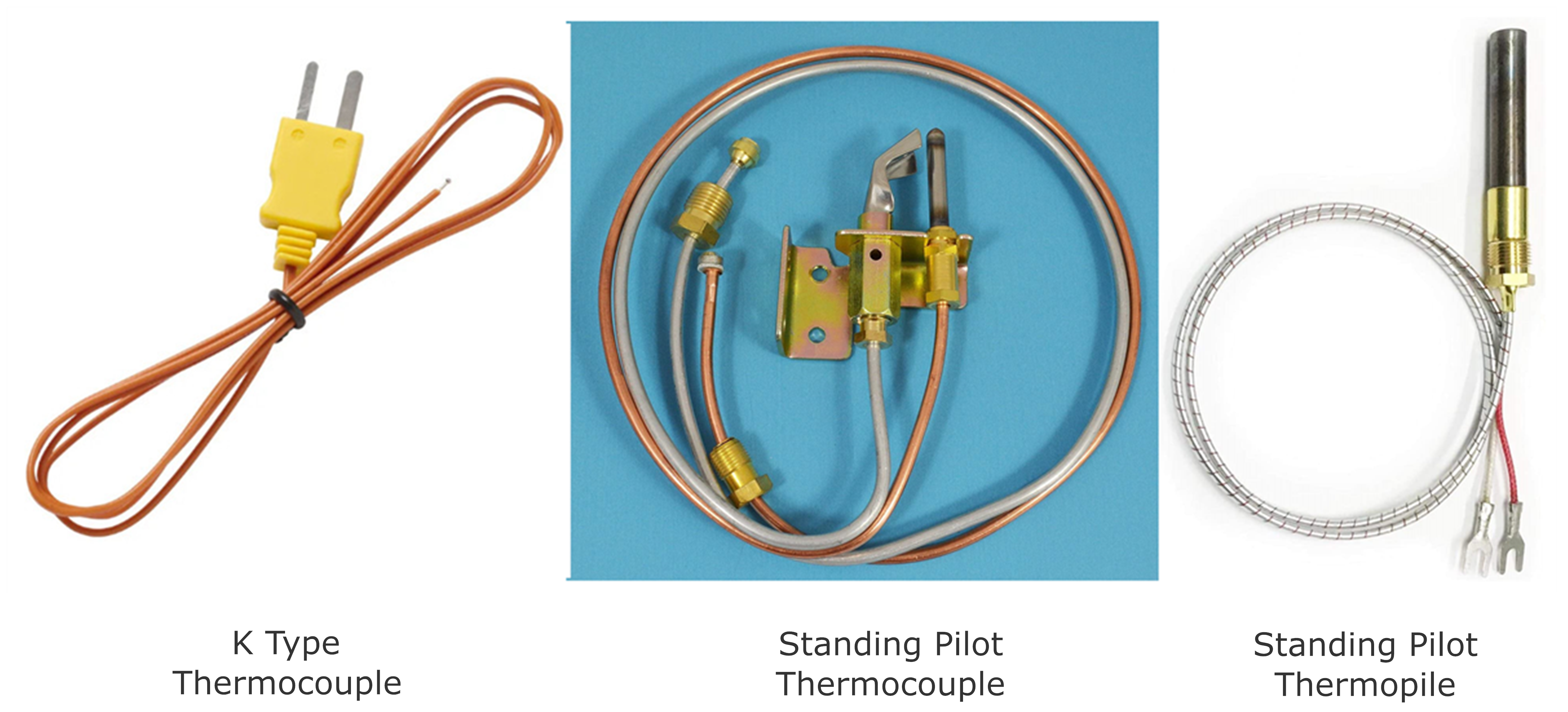
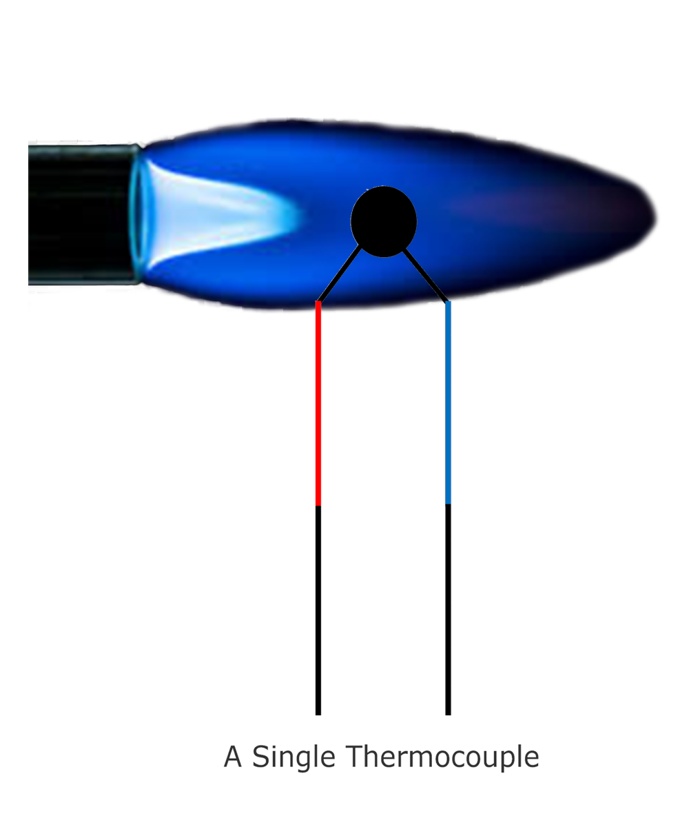
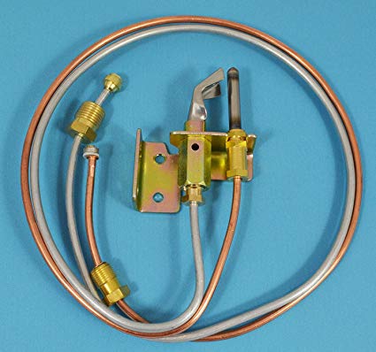
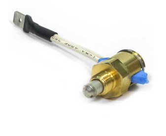
A single thermocouple (C Type) is used for a standing pilot system and generally produces around 30 millivolts. This voltage is used by the gas valve to keep the pilot valve solenoid internal to the main gas valve open. If the pilot goes out, the heat that is generating the potential (voltage) is lost, thus current stops flowing to the pilot valve solenoid, and the pilot valve is closed, closing off fuel to the pilot assembly. The thermocouple is a safety device. If the pilot flame goes out and the pilot valve doesn’t close, the burner compartment and potentially the room the equipment is in, can fill up with gas. The thermocouple must be fully engulfed by the pilot flame (impingement) at it's tip. If the pilot flame is getting weak, then servicing of the pilot system may be required.
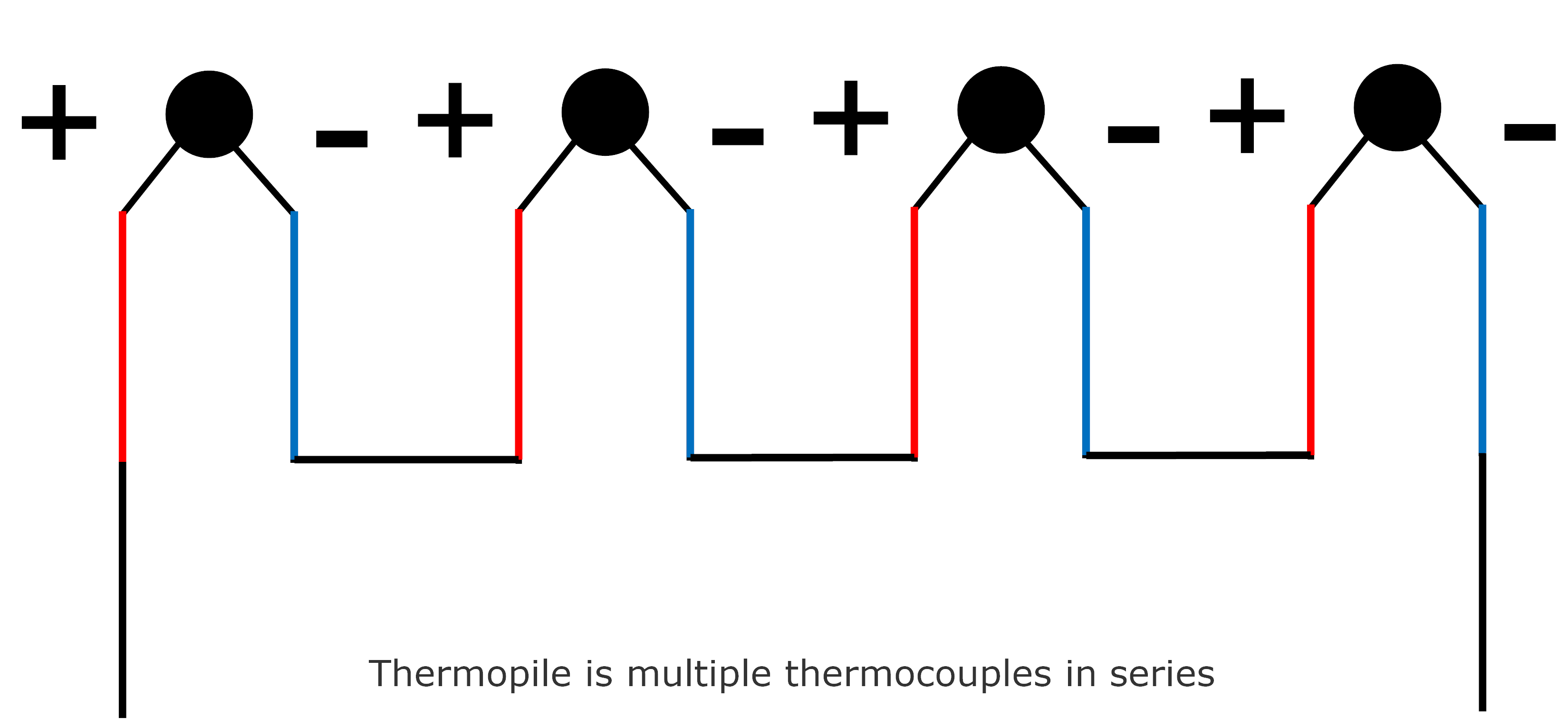
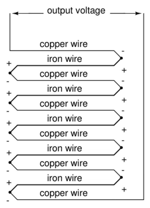
Multiple thermocouples are connected in a series configuration in order to produce more voltage in the case of a thermopile. A thermopile is used for a standing pilot system and generally produces around 600-750 millivolts. This voltage is used by the gas valve to keep the pilot valve solenoid internal to the main gas open and also provides the voltage needed to run the gas valve and safeties. If the pilot goes out, the heat that is generating the potential (voltage) is lost, thus current stops flowing to the pilot valve solenoid, and the pilot valve is closed, closing off fuel to the pilot assembly. The thermopile in this system is a safety device and a voltage generator to run the electrical system.
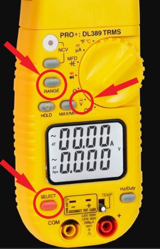
To check a thermocouple, you need a multimeter that is able to measure millivolts DC. It is typically shown as mVDC (might have to use the "Range Button") or is just the third decimal over on the DC voltage reading. Remember, the meter should be set to DC voltage (might have to use the "Select Button").
-
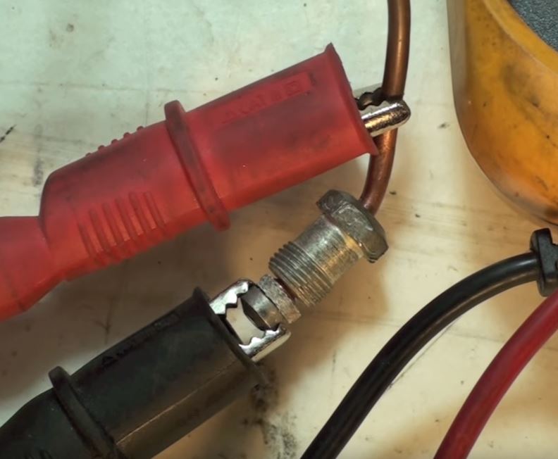
Disconnect the thermocouple from the gas valve.
-
Put one meter lead directly on the gas valve side of the thermocouple. Put the other lead on the copper line as shown in the picture below.
- Light the pilot. Most gas valves have a turn knob that has to be set from On/Off to Pilot. There usually is a push button that is pressed to manually open the pilot valve, sending gas to the pilot assembly in order to light the pilot. The push button must be depressed through the whole check. (With the thermocouple being disconnected from the gas valve, the pilot valve should not stay open and the flame should go out if the push button is released). The thermocouple typically needs to heat up for 30 to 60 seconds in order to obtain a proper reading.
-
30 mVDC is the desired reading, with a swing of plus or minus 5 mVDC. If the mVDC measurement is less than 22 to 25, I typically recommend replacement.
NOTE: In order to get the maximum voltage output, the thermocouple must be fully engulfed by the pilot flame AND the pilot flame must be hitting the tip of the thermocouple.
-
This measures the millivolts used by the coil in the electromagnet. A rule-of-thumb is this reading should be roughly half of the open circuit test above. It is taken using an adapter screwed into the magnet and the thermocouple screwed into the adapter.
-
This reading is taken the same as the previous reading except the burner is now on. With a proper flame, this reading should be about the same as the previous reading. With a lifting main burner flame or excessive drafts or chimney pull, this reading may reduce from previous reading (flame being pulled away from the thermocouple).
-
This is the final reading. It requires the pilot to be blown out. It measures the ability of the magnet to hold under reduced mVDC input. A good unit should drop out below 6 mVDC - normal is 1 to 2 mVDC. The allowable "drop out" time is 180 seconds. It is more likely to be 90 to 120 seconds. There will be an audible "click" when the magnet shuts down.
-
Dirty pilot assembly/orifice
-
Down draft in flue
-
Excessive draft (flame lift)
-
Combustion air issues (CAZ pressure)
-
Fuel pressure problems
-
Failing gas valve
Comments
0 comments
Article is closed for comments.